RCJuice University

RC Buggy Setup 101: Mastering Camber and Toe Angles with the SKYRC Setup Station

RCJuice University

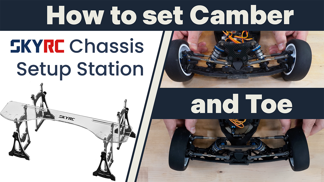
RC Buggy Setup 101: Mastering Camber and Toe Angles with the SKYRC Setup Station

by Mike RCJuice on Aug 04, 2024
Learn how to properly set up your 1/10 scale RC buggy using the SKYRC setup station. This comprehensive guide covers ride height adjustment, explains camber and toe angles, and walks you through the process of achieving the perfect baseline setup for your RC car. Gain valuable insights into RC car geometry and setup techniques that will enhance your buggy's performance. From understanding basic concepts to making precise adjustments, this video equips racers of all levels with the knowledge to optimize their RC buggy's handling and speed. Buy SKYRC Setup Station
RC Car Setup: Symmetry and Balance with SKYRC Corner Weight Scales

RCJuice University

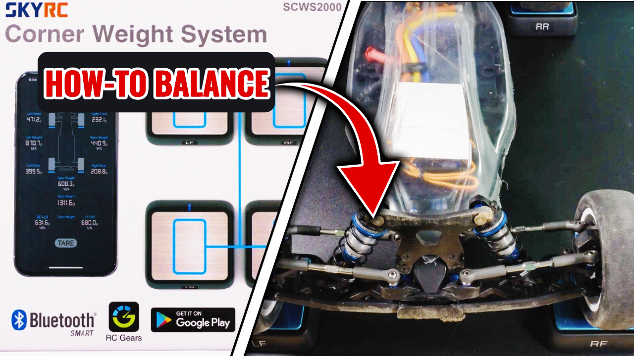
RC Car Setup: Symmetry and Balance with SKYRC Corner Weight Scales

by Mike RCJuice on Aug 04, 2024
In this video I explore the weight balance of the recently assembled RC10B7D buggy with SKYRC Corner Weight Scales. Follow along as I unbox the scales, label them, and effortlessly pair them with the RC Gears App. Then, I measure the initial weight distribution and experiment with different battery positions to see how much that actually affects the front-rear weight balance. Being a little curious, I conduct a crude test to observe how various exaggerated weight imbalances impact the car's handling. Finally, if you ever want to calibrate the scales but don’t have a 2000g weight, check out my creative solution using regular household items 😎 Buy SKYRC Corner Weight Scalers
SKYRC Tire Balancer Explained

RCJuice University

SKYRC Tire Balancer Explained: Technical Insights, Demonstrations & Guide to Solving Common Problems

by Mike RCJuice on Jul 26, 2024
In the following video we take a close look at the SKYRC Tire Balancer from every angle. We'll break down how this machine works, making it super simple to understand. Then, we'll walk you through how to use it, step by step, so you can follow along at home. We also address a few problems we found online or discovered ourselves. At the end we're turning our workshop into a mini science lab to show you why balancing your tires is a big deal for your RC car's performance. This video is your go-to guide for everything about this tire balancer and how to use it to get your wheels just right. Ready to dive in? Let's get those tires spinning perfectly! Buy SKYRC Tire Balancer Here
Getting into the Art of Radio-Controlled Car Racing: A Beginner's Guide

RCJuice University

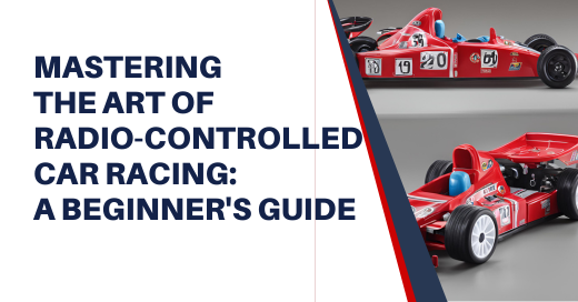
Getting into the Art of Radio-Controlled Car Racing: A Beginner's Guide

by Anton Piatkov on Jul 24, 2024
For a beginner the world of RC and RC-racing specifically seems crazy complex and hard to approach, the learning curve is pretty steep, with so many technical guides and jargon it is pretty intimidating. Instead, starting on your RC car racing journey should be an exhilarating experience filled with anticipation and discovery. So here is a guide on how to start it in a more approachable way, helping you ignite your passion for this exciting hobby.
History and Evolution of RC Airplanes

RCJuice University

History and Evolution of RC Airplanes

by Anton Piatkov on Jul 19, 2024
The journey of radio-controlled (RC) airplanes from simple, manually-operated models to today's sophisticated and technologically-advanced aircraft is a fascinating story of innovation, passion, and community. This article traces the evolution of RC airplanes, exploring how advancements in technology have transformed this engaging hobby and connected enthusiasts around the world.
What is so good about RC boats?

RCJuice University

What is so good about RC boats?

by Anton Piatkov on Jul 17, 2024
Imagine a sunny afternoon by the lake, the air filled with the electric buzz of excitement. Children and adults alike are gathered, their eyes fixed on the shimmering water where small boats zip back and forth with astonishing speed and agility. This is the world of Radio-Controlled (RC) boating, a hobby that captivates the heart with its perfect blend of high-speed action and intricate technical mastery. Whether it's the thrill of competition or the joy of casual sailing, RC boating offers an exhilarating escape from the mundane. This guide dives into what makes RC boating a beloved activity, exploring how technological advancements and community spirit converge to create a captivating experience for enthusiasts of all ages.
How to Choose Your First Ready-to-Run RC Car?

RCJuice University

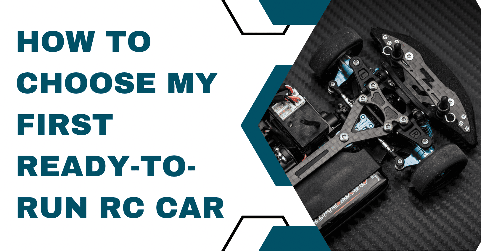
How to Choose Your First Ready-to-Run RC Car?

by Anton Piatkov on Jul 10, 2024
Embarking on the exciting journey of owning your first ready-to-run (RTR) RC car is thrilling but can also be a bit overwhelming given the variety of options available. This guide aims to simplify the process, helping you make an informed decision by addressing the key factors you should consider.
Why RC Car Racing is an Engaging Hobby?

RCJuice University

Why RC Car Racing is an Engaging Hobby?

by eStore Ninja on Jul 10, 2024
Radio-controlled (RC) car racing is more than just a pastime; it's an exhilarating hobby that combines technology, speed, and skill. The rise in popularity of RC car racing is evident as the market continues to grow. According to Research and Markets, the RC car segment is projected to reach nearly USD 2,800 million by 2031. This surge in interest underscores the dynamic and engaging nature of RC car racing.
Getting Started in RC

RCJuice University

Getting Started in RC

by Mike RCJuice on May 08, 2024
Radio-controlled (RC) cars, boats, and trucks offer a fun family hobby with lots of performance options. No doubt you have driven some type of remote-control vehicle over the course of your lifetime, but it was most probably a ‘toy class’ vehicle. The wonderful world of high-performance RC vehicles offers a variety of adrenaline-pumping options to fit every budget and experience level. These ‘hobby class’ vehicles go much faster than their ‘toy class’ predecessors offering a wide range of styles and sizes. Begin with Ready to Race In the beginning, most RC models had to be built from the ground up. You had to purchase the kit and hope that you assembled it properly. The radio system was also a separate charge as it was not standard with the unassembled kit. Now, things are much easier. Ready to Race (RTR) vehicles come fully assembled and complete with a working radio system. Of course, some people and families still choose to build their own RC cars. It’s a great way to spend some quality time with your partner and young family members. Once your dynamic RC vehicle is assembled it’s time to feel the need for speed. These little ‘hobby class’ vehicles are designed to perform and go lightning fast. They are built to withstand crashes and rollovers for the inexperienced driver spreading miles of smiles for all to enjoy. Types of RC Vehicles RC vehicles come in a variety of makes and models including cars, trucks, and boats. You can also choose between nitro and electric-powered vehicles. Typically, electric RC vehicles are quieter than their nitro counterparts making them the preferred model for those working within confined spaces. They’re also easier to operate and they require less maintenance than the nitro version. Electric model RC vehicles are typically recommended for beginners and younger sportsmen. However, nitro models allow you to refill the tank while the engine is still running which could potentially give you the lead you need to win a race. Electric battery packs drain with every use and eventually need to be charged or replaced. Both electric and nitro RC models have specific advantages, so you’ll have to choose what works best with your particular situation. Replacement Parts Regardless of make, model, or power source, you’ll eventually need parts for your RC vehicle. It may be a part of your vehicle’s routine maintenance or you may want to purchase special accessories to soup up your model. This is where RC Juice comes in. We take pride in providing excellent customer service while selling the highest quality parts at rock-bottom prices. If you are considering RC vehicles as a hobby or sport, or you already have an RC vehicle that needs some parts, contact RC Juice today to see how we can help.

RCJuice University

Servo Basics: From Digital Dynamics to Physical Build

by Mike RCJuice on May 06, 2024
Although one of the most simple electronic components in RC, as with most other components servos still have various specifications and designations which are important to understand in order to help you decide on the correct servo for your application. Configuration There are 3 main sizes categories under which servos fall.  Micro, standard (the most common size and what almost every 1/10 and 1/8 car uses), and giant (1/5 scale applications).  Within those sizes the specific measurements do vary between models and manufacturers, but most servos you will come across fall into one of these 3 categories. All servos have a 3 wire connector; one power wire, one ground wire and one signal wire through which the receiver sends signals to the servo to control it. Digital vs. Analog After size, the next most common general designation for a servo is the type; analog or digital.  The “guts” of each of these servos are the same, they differ only in how they process the signals they receive and how they operate the motor inside. Analog – Analog servos operate by pulsing the power to the motor inside, they do this at a rather slow rate of approximately 50 cycles per second.  At rest, they have no voltage going to them and they increase voltage to move the motor when the servo arm has a force applied to it, or when commanded to by the radio/receiver.  The voltage to analog servos varies based on what they are doing.  Since their frequency is rather slow, they are not very quick to respond to transmitter inputs and can also “overshoot” their final position. Analog servos have some degree of deadband to them as they need to build up some voltage across the motor to get them going (they are not responsive to very fine inputs). Analog servos do not hold their center position as well since they operate more slowly, if you were to turn the wheels of your RC car by hand while at rest, the servo would move a fair amount before it tries to center itself again as the power needs to build up to the motor.  The advantage to analog servos is that they are quiet and use less power since at they do not have any power going to them at rest. Digital – Digital servos have full power going to them at all times, this is why digital servos generally make noise when your RC is just sitting there with the power on. Instead of varying the voltage and cycle rate like an analog servo, a digital servo pulses full power but at a much quicker rate than an analog servo (closer to 400 times per second).  What this translates to is higher torque (and full torque at all times), much quicker operation and a servo that holds its position much more reliably than an analog servo. The only disadvantages to digital servos are the noise, and the slightly higher power consumption than an analog servo since they always have power going to them. Coreless, Standard and Brushless Standard servo motors are standard, brushed electric motors.  The motor has a steel core armature (rotor) wrapped in wire and that spins inside the motor housing/magnets. The disadvantage to these motors is that with their added weight, they take more time to start moving and are slower to come to a stop due to their increased inertia.  In a coreless design, the armature uses a very thin wire mesh that spins outside the magnets eliminating the heavy steel core which in turn provides much quicker, more powerful action.  Brushless servos use brushless motors (same theory as the brushless motors used to power your RC). These are very powerful, precise motors but are more complex to drive and are therefore more expensive. Ratings Voltage – Most servos have a range of standard operating voltage in which they operate.  The most common servos are rated from 4.8V to 6.0V.  High voltage servos are becoming more and more popular, and these are generally rated from 6.0V to 7.4V.  Obviously a high-voltage servo requires high-voltage input, some ESC’s have BEC’s with adjustable voltage, or an external BEC may be used to power the servo.  It is always important to ensure your receiver is rated for high voltage if using the ESC’s BEC to supply the voltage to the servo through the receiver.  It is also common to power high-voltage servos directly from 2S LiPo batteries. Speed/Torque – The 2 most relevant specifications to how a servo will operate are the speed and torque.  Almost every servo will show torque at 2 different voltages, since servos can operate within a voltage range the specs are shown for the minimum and maximum voltages.  As expected, with increased voltage comes increased power and speed.  Often, as speed increases the torque will decrease and vice versa.  Higher-end servos bridge that gap and provide both high-speed and high-torque but that comes at the price of added cost. The speed is shown as the time it takes the servo to rotate 60°, so a typical speed rating may look like this: 0.12 sec/60° @4.8V.  This means it will take the servo 0.12 seconds to rotate 60° with an input voltage of 4.8V.  While subject to opinion, in general any speed rating of under 0.15 seconds is a fairly quick servo, and speeds near 0.10 seconds and below are very quick servos.  High-performance aircraft servos are often in the sub 0.05 second range as stunt-flying requires very quick servo action. Torque is displayed ounce-inches, though sometimes you will see it displayed in kilogram-centimeters (easy to convert online by searching for “kg/cm to oz/in converter).  Since oz/in is the most common standard it is easier to compare servos in this format.  How does this rating translate to the real-world?  This rating is the amount of force the servo can apply to a 1-inch servo arm before stalling.  A servo with 100 oz/in of torque could lift 100 ounces with a 1 inch servo arm before stalling.  If the servo arm were 2 inches, it would be able to lift 50 ounces, and if it were ½ inch, it would be able to lift 200 ounces.  Torque decreases with a longer lever and increases with a shorter one. Torque ratings vary, but for a 1/10 vehicle like a buggy, short course truck etc. 150 oz/in is generally plenty of torque.  1/8 vehicles and monster truck with monster tires will have plenty of power with torque ratings in the high 100’s and into the 200’s (and beyond).  It is not rare to find servos capable of providing above 300 and 400 oz/in of torque nowadays.  Aside from using more power and costing more, there is no disadvantage to going with a higher rated servo.  In fact you may have to slow down the speed via radio programming if your servo action is too fast and providing twitch response. Physical construction Bearings  – Nearly all servos use ball bearings on the output shafts, some very inexpensive servos use brass bushings but that is not very common anymore.  Most servos will have either one or 2 ball bearings on the output shaft.  Having the extra bearing helps support the shaft when torque is applied to it, and helps the servo last longer while keeping “slop” to a minimum. Gears/output Shafts – With modern servos, metal gears and output shafts are very common.  Some very cheap servos still use plastic gears and shafts, but with the cost of metal-servos being as affordable as they are there is really no reason to consider a servo that uses plastic gears or output shafts.  The best servos use titanium for the metal components which also helps to reduce the weight and operating temperature.  Metal gears technically wear out more quickly than plastic gears, but they still last a very long time and replacement gear sets are often available. Water Resistance – Many servos are waterproof, which has the obvious advantage of allowing you to run your RC in wet conditions and not worrying about moisture damaging the servo. Waterproofing is achieved through the use of silicone gaskets/o-rings, waterproofing of the electrical components or a combination of both.

RCJuice University

Understanding ESC Ratings and Setup

by Mike RCJuice on May 06, 2024
An ESC, or “Electronic Speed Control” is the heart of your vehicles power system.  The speed control not only regulates the power from you battery to your motor, but it also regulates and provides power to your receiver which in turn supplies power to your servo and any other accessories you have connected to your receiver. Years ago, speed controls were mechanical devices which actually had moving parts to them.  A servo would physically move a lever on the speed control and regulate power to the motor, much like a dimmer switch regulates power to a light bulb.  Fortunately, the days of mechanical speed controls are long-gone and all ESC’s are now solid-state with no moving parts to them and, as with most electronic devices, they have gotten smaller and more powerful as they have evolved. Configuration ESC’s are generally designed to work with either brushed or brushless motors.  There are a few hybrid models on the market that are capable of running both brushed and brushless motors, but the majority of units are either-or. ESC’s, like motors, are available in either sensored or sensorless design.  A sensorless ESC can, of course, only run a sensorless motor.  A sensored ESC however is capable of running either a sensored or sensorless motor (see Motor section for information on sensored vs. sensorless motors). The two most common ratings for an ESC are the amperage and the voltage ratings.  The amperage is usually rated as a continuous amperage rating, and there is usually a “burst” amperage rating as well.  The burst rating is what the ESC can withstand for very short periods of time under heavy loads. The voltage rating is a minimum and a maximum rating, there is no “burst” rating for voltage.  ESC’s are designed to run with a specific minimum and maximum voltage.  Almost all ESC’s have a minimum voltage requirement of 2S (7.4V), and the maximum voltage varies greatly.  Most 1/10 ESC’s have a maximum of 3S (11.1V), and 1/8 ESC’s generally have a maximum rating of either 4S or 6S (14.8V or 22.2V).  Larger ESC’s for 1/5 scale applications can run much higher voltages than 6S but are less common. The majority of ESC’s cannot run on 1S (3.7V), ESC’s for 1S use are usually specific models for specific applications and can only run on 1S. A few models can run 1S and higher voltages but they are not very common. Picking the right ESC Picking the right ESC for your application can be very confusing, as there are more things to consider than simply the amperage and voltage ratings.  For example, the 2 ESC’s below both have a 120 amp rating but are intended for very different applications.  The 120A Turbo Competition ESC is rated for 2S-3S voltage, though it is generally run in applications using 2S since it is a 1/10 competition ESC and only 2S is permitted in 1/10 racing. This category of ESC is generally used in 1/10 2WD buggies/stadium trucks/SCT’s and in 4WD 1/10 buggies running 2-pole 540 sized motors and are not suitable for a heavier vehicle like a 4WD SCT.  This ESC also incorporates many adjustable features like adjustable turbo and boost timing, along with a “blinky” mode for stock class racing with the vehicles mentioned (see Timing section for an explanation on ESC timing).  The 120A 2S-6S ESC, although it is rated for the same amount of amps, is rated for use with anything from 2S all the way to 6S.  This category of ESC is generally used for a heavier vehicle like a 4WD SCT and in 1/8 buggies, both of which utilize larger, 4-pole motors.  This ESC is physically much larger that the 120A Turbo ESC and can therefore dissipate much more heat and do so more quickly.  This category of vehicles generally do not use ESC timing so most ESC’s in this category will not have adjustable timing. When it comes to amperage ratings on an ESC, this is a good example of when “bigger is better” applies.  As long as the ESC physically fits in your vehicle, it is always advisable to go with the highest amperage rating your budget allows.  It is cheap insurance, and there is no disadvantage to a higher amperage rating. It does not consume any more power and will only make your power system more robust. It is also important to realize that an ESC is part of your complete power system, all of which needs to be set up properly for all the individual components to function as intended.  Just because an ESC is 6S capable does not mean you can connect it to any 6S motor and expect good results.  Gearing needs to be correct for the vehicle setup, taking into consideration overall gear ratio (to include pinion/spur ratio, transmission ration, diff ratios and tire sizes) and motor KV.  A motor geared too tall can pull excessive current through an ESC and damage it, or overheat to the point where it shorts out the ESC.  Please see our “Power System Setup” section for more information on gearing and temperature monitoring. As you can gather, it can be difficult to decide on which ESC to pick for your particular application since there are so many factors.  If you are unsure, it is always advisable to reach out to us at RCJuice and we will be more than happy to provide some guidance as to which ESC is best for your application. Installation & Setup An ESC should be firmly and securely installed in your vehicle, and optimally should be mounted where it will receive good airflow during operation.  Heat and vibration kill electronics, so anything done to reduce these will increase the life of your ESC. When running a sensored motor, the wires must be connected in the appropriate order.  Your motor and ESC will each have terminals marked with “A,B, C” designations, and each must be connected to its corresponding letter on each component.  When running a sensorless motor, the wires can be connected in any order.  If the motor runs in the reverse direction than desired, simply reverse any two wires and motor direction will be reversed.  If a sensored motor runs opposite of the direction desired, it must be reversed through ESC programming. It is also advisable to always use a polarized power plug (directional plug that can only be plugged in one direction).  If an ESC is connected to a battery with the leads reversed, the ESC is usually instantly destroyed.  In race vehicles it is very common to run simple bullet plugs on the end of the power leads that plug directly into bullet packs, this is to avoid excess connections that can increase resistance and possible failure points.  Even experienced racers will almost always inevitably at some point plug in an ESC backwards while rushing to make a race and “pop” their ESC. Calibration Anytime a new ESC is installed, or any time your radio/receiver are swapped it is critical that the ESC be calibrated.  Without calibration, an ESC does not “know” what the maximum throttle and maximum brake inputs from the radio are.  It is like connecting a carburetor to throttle linkage and never adjusting it, it may be correct if you are lucky, but it also may not be opening or closing fully.  ESC’s have a variety of different methods of calibrating depending on the model, but they all consist of putting them into a calibration mode and using your radio to apply full throttle, full brake and neutral signal input to it and confirming each step.  It is also very important that your throttle and brake end points (also called EPA or “travel” depending on radio model) be set to their maximum setting before calibration. Depending on radio model this may be 100%, 120%, 150% etc.  In addition, some radios must have the throttle channel set to “REV” before calibration.  If after calibration your vehicle goes much quicker in reverse than it does forward that is an indicator that your throttle channel must be reversed and calibration performed again. Cut-off Voltage When using LiPo batteries, it is important to make sure your voltage cut-off is set according to the batteries being used.  The majority of newer ESC’s auto-detect the number of cells being used, so the value that is changed is the voltage per cell.  An ESC does not know what individual cell voltages are, so it uses the total pack voltage to activate cutoff.  For example, if you are using a 2S pack and cutoff is set to 3.2V, then when total pack voltage is at 6.4V then the cutoff will be activated.  This is one of the many reasons it is important to have well-balanced batteries. If you are running NiMh or NiCd batteries, the cut-off feature must be turned off.  These batteries are not damaged by running them low on voltage as lithium batteries are, and since their nominal voltages are different than those of lithium batteries the ESC may activate the cutoff when the pack still has plenty of charge left in it. Timing As mentioned earlier, some ESC’s have the ability to adjust timing via “Turbo” and/or “Boost” settings.  Increasing timing via the ESC is the same as increasing the timing on a motor that has a physically adjustable end-bell, it increases power but it also decreases system efficiency and increases heat. Turbo and boost timing are usually highly adjustable, but here is a general explanation of how they work: Boost – When timing is added via the boost setting, the ESC will increase timing when the motor is within the programmed RPM range.  For example, boost can be set to add 30 degrees of timing between 10,000 and 30,000 RPM.  The amount of timing added within that RPM range is also adjustable on most ESC’s with boost timing, meaning that at 10,001 RPM’s you may get 1 degree of additional timing, and it will increase up to 30 degrees of timing progressively until the motor reaches 30,000 RPM. Some ESC’s also permit you to adjust this “slope”, or the rate at which timing is applied in the RPM range programmed.  Boost timing is used for overall power increases in a power system setup. Turbo – Turbo timing also adds motor timing, but the activation method is different than boost timing.  With turbo timing, timing can be added when the throttle is at the maximum setting, when the motor is at a pre-set RPM or a combination of both.  Additionally, turbo timing can be delayed by a pre-set amount so that it will only be added when the pre-set conditions are met for more than a pre-set time.  Turbo timing is used when a track has a long straight where additional power is needed. Depending on the ESC, turbo and boost may also have further adjustment points such as adjustable “slope” where the rate at which timing is applied is adjustable, multi-stage adjustments where timing can be increased at different amounts at different amounts of throttle/RPM and more. Again, this depends on the specific ESC but this is a general explanation of turbo and boost timing. Blinky Mode – In stock class racing, ESC timing is not allowed.  Most race-grade ESC’s have what is called “blinky” mode.  In this mode, no ESC timing is added, and the LED light on the ESC constantly flashes while in this mode indicating that no ESC timing is being used and giving this mode its name. Other common settings Mode – Most ESC’s can be configured so that forward, reverse and brake functions are available, so that only forward and brake is available (also called “race” mode since reverse is not allowed in racing), or so that only forward and reverse are available (no brake). Punch (Initial Acceleration) - This setting controls how fast power is applied based on throttle input.  A 0%, or Low setting disables punch, and throttle is applied to the motor as fast as you pull the trigger on your radio.  A 100% or Maximum setting means the punch feature is working as hard as it can to apply throttle as smoothly and softly as possible (some ESC’s are reversed where a “0” setting limits throttle input the most).  This is helpful with 2WD cars on low traction, when you are concerned with tire ballooning/parts breakage, traction coming out of turns etc. Maximum Forward/Reverse Speed – This simply controls the maximum amount of throttle applied in both forward and reverse directions. Brake Force – This controls the maximum braking force that will be applied when the brakes are used. Drag Brake – This controls how much braking the vehicle will have when coasting in neutral.  This is helpful for cornering on a track to avoid having to physically reverse the trigger for the little braking needed in smooth turns and keeping your corner speed up. Motor Rotation – Some ESC’s allow you to change the direction in which the motor rotates.  This is used on sensored setups when the setup has the motor rotating in the opposite of the direction needed since you cannot reverse motor direction by swapping two wires as you can with a non-sensored system. Motor-Timing – Some ESC’s allow you to add a fixed amount of motor timing. In contrast to boost and turbo timing where you have almost infinite adjustment of when and how much timing is applied, this setting generally has settings like “Very Low”, “Low”, “Neutral”, “High” and “Very High”. It is important to realize that this is still adding motor timing and can greatly increase operating temperatures. Neutral Range (Deadband) – This is the amount that you will need to move the throttle before the ESC begins to respond.  A higher value means you will have to move the throttle more to activate the ESC and will make the throttle less “touchy”. Programming and Firmware ESC’s have a variety of different ways in which all of these settings can be adjusted.  The most basic method that some ESC’s employ is to use the “Set” button on the ESC and a combination of counting flashes on the LED and listening to motor beeps.  This is convenient because no other hardware is required, but can be very confusing as you step through multiple levels of programming as it is easy to lose track of flashes, beeps and your position in the programming sequence. Program Cards – Many ESC’s have programming “cards” or “boxes” available for them.  This is a handheld device which plugs into the ESC and allows you to change the settings.  The ESC needs to be connected to battery power, and if not then an external power supply needs to be used to supply power to the program card. Some cards also function as a USB link. USB Links – Many ESC’s also have a USB link available for them.  This allows you to connect your ESC to a computer, and using an application from the ESC manufacturer you are able to make adjustments to ESC settings.  These are also used when updating the firmware of an ESC as those need to generally be downloaded to a computer before being sent to the ESC. WiFi – Many newer ESC’s also have WiFi or Bluetooth modules available for them.  These simply allow you to use your phone as a program card and allow you to connect to your ESC via Bluetooth or WiFi connection. The “Firmware” is the operating program that is loaded into an ESC.  It is what the ESC uses to conduct all of its operations, and often manufacturers offer updated Firmware programs to add new features to, or to fix bugs in an ESC’s operation. BEC’s Almost all modern ESC’s have a built-in BEC, or “Battery elimination circuit”.  This is another name for a voltage regulator.  What these do is convert battery voltage of differing amounts (varies depending on what battery you are using) and converts it into a stable voltage to be sent to your receiver/servos/other accessories.  Many times the battery pack being used would supply far too much voltage for receivers and servos and would destroy them, so that voltage needs to be regulated to a usable, and stable amount.
RCJuice University

Selecting the Right Motor for Your RC Car

by Mike RCJuice on May 06, 2024
Along with LiPo battery technology, brushless motors have been one of the biggest technology leaps in our hobby.  With brushed motors, electric RC vehicles were quiet, simple, and clean to operate but the power could not match their fuel burning counterparts.  With the advent of brushless motors, the tables have turned and now electric cars have power surpassing what is available from a piston engine along with the simplicity that goes with an electric powertrain. So what exactly is a brushless motor?  The inner workings of a brushless motor could be the subject of an entire article in of itself, but the basics are easy to understand.  All electric motors work on the principle of magnetism, and the fact that like-poles of a magnetic field repel each other.  The windings of an electric motor are constantly reversing their pole via electricity, and this pushes the magnets past them.  An electric motor is in a constant state of repelling magnetic fields which in turn spins the rotor inside of it. Brushed motors In a brushed motor, the motor housing contains the magnets, and the stator (windings), are on the rotor that spins inside the motor can.  Since the rotor is spinning, there needs to be a way to supply power to those windings without having wires connected to it.  This is where brushes come in; brushes are carbon pieces that conduct electricity and are physically contacting the end of the rotor to which the windings are connected. Spring pressure holds the brushes against the rotor so that as they wear they stay in constant contact with the rotor.  Have you ever seen sparks coming from a brushed motor during operation?  This is coming from where the brushes are contacting the rotor.  The downsides to brushed motors are quite obvious; the brushes physically wear out as well as the surface of the rotors where the brushes contact, and there is friction and heat created from the contacting surfaces.  Brushed motors require rebuilding during their life cycle which involves refreshing the rotor contact surface by cutting it on a lathe, and replacing the brushes when they are worn.  The advantage to a brushed motor is that they have very smooth operation at low speeds, the current is easy to control since there is a physical connection and this is why vehicles that normally operate at low speeds can still benefit from brushed motor.  RC crawlers are one class of vehicle that still widely use brushed motors.  Below is a diagram which illustrates the principle of a brushed motor. Brushless motors (to the rescue!) It’s pretty obvious that having so much friction inside something that we are trying to make power with is not a good thing.  Friction builds heat, robs power and greatly reduces the efficiency of the motor.  A brushless motor is, as the name implies, an electric motor that has no brushes.  A brushless motor ingeniously flips the conventional motor design around which eliminates the need to send electricity to a constantly moving part.  In a brushless motor, the magnets are on the rotor, and the stator windings surround the rotor inside the motor housing.  You may ask yourself why this was not the original design of the electric motor since it is much simpler than a brushed motor, and the answer to that is in the complexity of controlling the power to the stator.  In the brushed motor, all of the “switching” is simplified in the fact that as the rotor turns, different contacts are exposed to the brushes and only the ones in contact will receive power.  A brushless motor requires a specialized speed controller to run it capable of switching the power electronically inside of it and at incredibly high speed, and brushless ESC’s accomplish this through the use of forward energy transistors, or FET’s.  The brushless DC motors we use in our RC’s are actually closer in design to a 3-phase AC motor, hence the 3 wires on brushless motors.  Since the “driving force” of an electric motor is accomplished through magnetic fields, the only friction in a brushless motor comes from the bearings on which the rotor rides. The diagram below illustrates the operating principle of a brushless motor, the stator windings around the stator plates constantly alter the magnetic poles surrounding the permanent magnets of the motor causing the rotor to spin. Motor Sizes Motor sizes can be a confusing subject, as there is no consistent standard for motor sizing.  In general, there are motors for minis (1/18, 1/16 etc.), 1/10, 1/8 and 1/5 scale, with quite a variety of sizing within those scales.  Many motors are referred to by a number, such as 540, 4068, 4076 etc.  A 540 motor is 540mm long (and 36mm in diameter), a 4068 is 40mm wide by 68mm long, a 4076 is 40mm wide and 76mm long and so on. You will often see 1/8 motors listed as either 40 or 42mm wide, the difference is in the additional diameter that comes from the “fins” on the motor cases.  The actual can is 40mm wide but the fins add an additional 2mm to the overall width.  Since there is no standard for nomenclature it is confusing because some names refer only to the length, and some to the length and diameter of the motor. For 1/10 vehicles, the most common motors are 540 and 550 motors.  Both of these are 36mm in diameter but the 550 is 10mm longer.  The longer rotor helps products more torque, so these motors are geared towards heavier 1/10 vehicles like short course trucks. The most common 1/8 motors are either 68mm for buggies, or76mm for truggies and monster trucks (again, the longer length for additional torque in the heavier vehicles). These are the basics of motor size, but it should be pointed out that there are a seemingly infinite amount of motor sizes out there from many different manufacturers with most of the variety coming in the lengths.  Below is an example of some of the most common motor sizes next to each other for comparison. Turn/KV Motors are rated by either “turn”, or “KV”.  Before brushless motors came into our hobby, brushed motors were rated by how many times the wires were wrapped around inside the motor, or how many “turns” of wire there were.  When referring to brushless motors, the most common rating you will see is “KV”, which stands for “kilovolt”.  Some brushless motors, however, are still rated by “turn”, with the most common being 540 2-pole competition motors and they will still usually have a corresponding KV rating.  The only reason for this is that in racing, the “turn” rating was used for so many years that it is just a more common nomenclature when referring to motors.  There is no physical difference between motors that are rated by turn or KV, it is only a difference in name. KV has become the more common rating for a motor as it is more easily visualized than turns, higher KV’s mean higher RPM’s where with turns, the lower the number the higher the KV’s/RPM.  For every kilovolt, a motor will turn one RPM per volt of electricity supplied.  For example, a 4000KV motor on a 2S/7.4V LiPo will spin to 29,600RPM (4000 x 7.4 = 19,600). Understanding how KV relates to a motor in use is absolutely critical to picking the correct KV for your car and keeping it running well once it is installed.  A higher KV motor can spin to a higher RPM at a given voltage than a motor of a lower KV, but the trade-off is in torque.  Higher KV motors have less torque, so they have to work much harder to propel a vehicle to higher speeds and the trade-off is in increased heat and power consumption.  A higher KV motor will also draw down a battery quicker than a lower KV motor.  Many guys make the mistake of thinking they can simply switch to a higher KV motor to go faster.  While this is true to a degree, it is unfortunately not that simple.  Visualize a car that is stuck in 1st gear, and a car that is stuck in 5th.  The car stuck in first gear will take off nice and quick and there is not much load on the motor, the car in 5th will have to work incredibly hard to get going, and the engine would get very hot due to this load.  Translated to an RC car, a higher KV motor needs to be geared lower to not overload/overheat.  Gearing down lowers your top speed, so while you can still go faster with a higher KV motor it will not be able to simply add as many RPM’s to your car as compared to the lower KV motor on the same battery.  Brushless motors make great power, but the laws of physics still apply and nothing, when it comes to energy, is free.  If you simply substitute a higher KV motor and  leave the gearing the same it is very likely that you will overheat your motor to the point of failure, and in extreme cases it can take the ESC out with it. You will often see motor KV’s rated to a certain voltage (2S, 3S etc.).  There is nothing in a motor that physically limits or controls the amount of voltage you can run to it, a motor that is rated to run up to 2S would run fine on 3S, but it will likely overheat quickly and fail. For the majority of applications it is important to adhere to the voltage guidelines provided by the manufacturer. The way to determine if your motor is operating in the “safe” zone is by monitoring the motor temperature.  The best way to do this is with a temperature gun, a general rule is to keep your motor under 180F.  If you do not have a temperature gun, you can feel the motor (use EXTREME CAUTION as an overheated motor can burn your finger very quickly).  If you can’t comfortably leave your finger on the motor for 2 or 3 seconds, it’s safe to assume the motor is too hot.  Motor temps and gearing are covered in more detail in our “Brushless System Set-Up” article. Sensored vs. Sensorless The most basic brushless motors are sensorless motors, they only have the 3 power wires running to them and the order in which these wires is connected does not matter.  If the motor turns opposite of the direction you need it to run in, you can simply swap any 2 of the wires.  In a sensored motor, there is an additional harness plugged into the motor, and the motor connections are labeled as “A, B & C”.  The wires must be connected in the appropriate order for the motor to operate correctly, if the rotation needs to be reversed it must be done via ESC programming.  To easily understand the difference between a sensored and sensorless motor, visualize the operation of a brushless motor as a chain reaction that needs to happen in a specific order.  Power starts flowing, magnetic fields are created and the rotor starts to spin due to the force of repelling magnetic fields.  The problem is that the ESC needs to apply the correct polarity to the correct section of the stator depending on which position the rotor is in for this chain reaction to work nice and smooth.  In a sensorless motor, the chain reaction starts “where it left off”, and sometimes the rotor is in the wrong position for the reaction so you get what is commonly referred to as “cogging”.  This is the jerky operation of a brushless motor when taking off from a stop and at low RPM.  Certain parts of the rotor may be repelled, but others may be attracted to the magnetic field so the motor is fighting itself until RPM’s build and the chain reaction begins to work in harmony.  A sensored motor uses a hall-effect sensor which can tell the ESC exactly what position the rotor is in, so the ESC is able to fire in the exact sequence it needs to for motor operation to be nice and smooth right from the start. Poles You may see motors referred to as 2-pole, 4-pole, 6-pole and we are starting to see even 8-pole motors.  This is referring to the number of magnets that are on the rotor.  With more magnets, the motor can make more torque as it is receiving more “pushes” per rotation of the motor.  The trade-off is in high RPM operation, once the rotor starts to spin very quickly it is harder to control the increased number of pulses per rotation and that has an effect on the smoothness and control over the motor at higher RPM’s. Timing Some race oriented motors have housings that are marked with different “degrees”, and you can adjust the timing by loosening some screws and moving the motor housing to the desired position.  When you adjust a motors timing, you are changing the relation of the rotor to the stator when the firing of the phase occurs.  Adding timing is like getting a head-start on the chain reaction each time that phase fires, so the motor can make more power with additional timing.  As usual, there is a trade-off and as is usually the case the trade-off is in heat and efficiency.  Increasing timing is reduces the efficiency of the motor; the more timing the less efficient it gets, the more heat it builds and the quicker it will run down your battery.  It is important to make timing changes in small increments and closely monitor motor temperatures to ensure the motor is staying under 180F.

RCJuice University

Lipo Battery Basics

by Mike RCJuice on May 06, 2024
So you want to know what all those numbers mean? Lipo batteries have revolutionized our hobby, there is no question about it. There is a wealth of information you can find online about Lipo batteries, but there is still a lot of confusion about them and some safety precautions that you need to follow which prompts some people to stay away from Lipos. Hopefully the information here will shed some light on Lipo batteries and the basic terminology you need to know so that if you haven’t made the leap to Lipos yet you will give them a try! LIPO BASICS Historically, the batteries used in RC were big, heavy, low on power, and didn’t last very long.  “Lipo” is short for “Lithium Polymer” which is the technology used to make Lipo batteries.  Lipos are very similar to a more common technology that you have probably seen in countless applications called “Lithium Ion”.  They are similar in that they both have nominal cell voltages of 3.7 volts, but dissimilar in that Lipos do not have a hard metal casing like Li-Ion batteries but rather have cells which are encased in a foil based flexible “pouch”.  Additionally, while Li-Ion batteries use an organic liquid solvent as the electrolyte, Lipo batteries use a dry electrolyte polymer that resembles a thin plastic film.  If you were to cut open a Lipo battery you would be able to unfold the film and it would be several feet long (depending on the size of the battery).  This construction allows for a very thin battery along with a wide range of sizes and shapes of batteries. Lipo batteries (along with significant advances in brushless motor technology) have finally been able to provide the types of power previously only attainable with nitro engines.  The run times are substantially better than older battery technology, and not to mention electric is much cleaner, easier to use and has none of the endless tuning associated with nitro.  These features of Lipo technology have propelled more and more people to get involved in RC which has been great for our hobby. TERMINOLOGY Voltage and “S” rating Lipo batteries consist of one or more “cells”, which you can think of as an individual battery.  When a Lipo has more than one cell, they are wired in series so that the voltages add up.  The nominal voltage for each cell is 3.7 volts.  You may have seen Lipos referred to as “1S”, “2S”, “3S”, and so on.  The “S” represents a “Cell”, and the number before it is simply the number of cells the battery has. You may wonder why this is not called a "C" versus an "S", but it is referring to the fact that the cells are a certain number of cells wired in "Series".  This, by default determines the nominal voltage of each battery.  A 1S battery is a 3.7v battery, a 2S is a 7.4v battery, a 3S is an 11.1v battery and so on.  The more volts you have the faster your motor will turn, but in turn this also creates more heat.  It is also important to know how many volts or how many “S” your ESC is rated for so that you do not destroy it with too much voltage.  You also need to take into account how many KV your motor is rated for so that you do not spin it too fast.  If you multiply the KV rating of a motor by the voltage of a specific pack it will tell you how fast that motor will turn with that battery (as long as the ESC and the motor itself can handle it).  For example, a 4000kv motor with a 2S/7.4v Lipo will spin to 29,600 RPM (4000x7.4). “C” Rating A Lipo’s “C” rating is probably the most misunderstood designation of Lipo batteries.  The “C” rating is a rating which tells you how fast the battery is capable of discharging its power.  Think of it as the size of a water hose, the bigger the hose (or the higher the “C” rating”), the faster the current can come out of the battery.  Most Lipos have a “Continuous” and a “Burst” rating.  The “Continuous” rating is the “C” rating that the Lipo can put out on a constant basis, and the “Burst” rating is how much it can put out for brief periods of high draw. A battery will only discharge as much power as is being pulled from it by your electronics.  So if you have a basic system which is not very power hungry you do not need to spend money on a higher “C” rated battery as there is no need for it. That being said, the higher the “C” rating of a Lipo the cooler it is going to run and the longer it will last as you are not “working” it as hard.  People who do aerobatic or 3D flying and those who have high power systems in their cars or trucks can really benefit from Lipos with higher “C” ratings. A 30C rating is typically enough for the majority of applications you will run across, with the higher “C” ratings being used for the high performance applications mentioned above.  When in doubt though, always go with a higher “C” rating, you can never have too much in this department. A good “seat of the pants” way of checking your batteries to see if they are being over worked is to feel them immediately after using them.  As a general rule, if a pack is too hot to hold comfortably in your hand then you should switch to a higher “C” rating. Capacity, or “mAh” The capacity of a Lipo battery, or the “mAh” rating is the same unit of measurement as used for other types of batteries.  The mAh rating is the capacity of the battery (measured in ampere-hours), like the size of a gas tank in a car. Once you know the “C” rating and the “mAh” rating of a Lipo, you can determine the available current from that battery.  All you have to do is multiply the “mAh” rating by the “C” rating and it will tell you how many amps of power that battery can provide.  For example, if you have a 2200mah, 30C battery then you can safely provide 2200mAh x 30 = 66,000 mAh, or 66 amps with that battery.  If you know the current requirements of your electrical system you can use this formula to determine if you have the right battery. Safety A lot of the fear and mystery about Lipos revolves around stories of Lipos bursting into flames while using them or while charging them.  While these certainly are possible occurrences with lipo batteries, if you understand some basics and take the proper precautions then you will greatly reduce the possibility of a mishap. Over-charging, Over-discharging The majority of accidents with Lipos happen when they are either charged well beyond their rated voltage, or when they are discharged below their minimum voltage.  Each cell should never be charged to more than 4.2 volts (which is a 100% charged cell) and as a general rule should not be discharged below 3.2 volts per cell.  Some people may argue that you can go down to 3.0 volts per cell, and while that may be true it is getting dangerously low and may shorten the lifespan of your battery. It is extremely important that you use a charger designed specifically for Lipo batteries and that you have it set correctly (this will be discussed more in the charging section). A proper charger will ensure that your battery is not over-charged, and most ESC’s nowadays are designed with Lipo settings built in. Most ESC’s have an “Auto-Lipo” mode where it detects the number of cells in the pack and therefore will sense when the overall pack voltage is at or below the minimum voltage programmed into it, which is generally 3.2 volts per cell.  Most ESC’s are also programmable and allow you to select the cutoff voltage manually as well.  It is critical that you ensure that your ESC is set for Lipo mode or else damage to the batteries, electrical system or vehicl ecan result.  If you are using an older ESC or one that simply does not have Lipo mode, it is important that you install an external LVC (Low Voltage Cutoff) which can cut power once the voltage gets too low. General Rules Use only a charger designed for Lipo batteries. Make sure the correct cell count is displayed on your charger.  Keep an eye on the charger for the first couple minutes of charging to make sure that the setting remains the same. Balance charge your packs periodically.  As a rule, you should balance charge your pack every 10th charge, but it is easy enough to do more often than that.  This is explained in the charging section. Never leave a charging battery unattended. Charge batteries on a safe surface and away from anything that may catch fire should something go wrong.  Fireplaces, concrete surfaces away from flammable items, flower pots and pyrex dishes with sand in them are ideal spots. Use a Lipo charging bag.  There are special fire retardant bags made for charging Lipos that will contain any flames should a pack catch fire while charging.  These are available in our "Battery Hardware and Accessories" section. NEVER puncture a cell.  If a pack balloons or puffs up, set it aside in a fire safe area for at least two hours and then discharge it slowly before discarding.  Slow discharging can be accomplished with a charger which has a discharge feature, or you can wire a flashlight bulb of appropriate voltage to the pack (higher voltage is OK, lower voltage is not).  Once the light is completely out you can discard the battery. Check your pack after a crash.  A Lipo pack involved in a crash may look OK from the outside but may be shorted out internally.  It’s a good idea to remove and set aside a pack involved in a crash for at least 20 minutes to make sure that it does not short out. Charge batteries in a ventilated area.  Should something go wrong, hazardous fumes may spew from the battery. Keep a fire extinguisher or bucket of sand nearby in case of fire. Remember, as long as you follow all of the precautions it is very unlikely that you will have an incident with your Lipos, but it is always best to be prepared! Charging As cool as Lipo batteries are, they aren’t much good to us if we can’t charge them back up after using up the power! The first thing to know is that you MUST use a charger designed specifically for Lipo batteries.  Lipo chargers range anywhere from under $10.00 for a charger that is little more than a plug in wall transformer with some voltage detecting circuitry, to high current models that cost several hundred dollars.  The different models and types of chargers are a whole other subject but the important part is that they are specifically designated as Lipo capable. A Lipo charger has to be able to know how many cells a particular pack has in order to not over charge the pack.  Most chargers can do this automatically or you simply select the number of cells that you have when you charge your pack.  Once the pack starts charging, it’s a good idea to keep an eye on the charger for the first couple of minutes to ensure that it remains in the correct setting. Charging Rates – The rate at which a Lipo battery may be charged is also expressed in a number of “C”, just like the discharge rating.  This number is lower than the discharge rating though and is usually around 1C to 5C.  If you do not know the charging rate of a particular Lipo pack, assume that it is a 1C rated pack.  What the “C” rating means is at how many times the capacity of the battery you should charge it at.  For example, at "1C" a 2000 mAh pack should be charged at no more than 2 amps (2000 x 1 = 2000mAh, or 2.0 amps).  If you were charging this same pack at a rate of 2C, you could charge it at 4 amps (2000 x 2 = 4000mah or 4.0 amps).  While 1C charging rates used to be the norm, advances in Lipo technology have allowed most batteries to charge in the 2-5C range.  It is important not to exceed the recommended charging rate or you may shorten the battery life or risk a fire. Balance Charging -  Earlier, in the safety section we mentioned balance charging.  It is important to periodically balance charge any Lipo pack with more than one cell in order to keep all of the cells at or near the same voltage.  The reason that this is so important is that because once in use, the ESC only sees the overall voltage of the pack and activates the Low Voltage Cutoff accordingly to prevent battery damage, or worse yet, a fire.  If you have one weak cell in say a 3 cell pack, the ESC may not know this because the other 2 cells are charged up enough to keep the overall pack voltage up and the one cell may become discharged below 3.0 volts.  Only one cell has to become over-discharged to cause a fire or damage the pack. Because of this, nearly all modern Lipo batteries have balancing taps on them.  This is the smaller set of wires coming out of the pack with a small connector on them.  Through this connector, a charger can measure the individual voltage of each cell and stop charging if there is a problem with one or more cells. Since it knows the voltage of each cell, a balancing charger is able to charge individual cells more or less in order to "balance" the pack. Through regular use the individual cell voltages can begin to creep away from each other which is why it is important to balance charge your packs at least one in every 10 charging cycles. That's It! So there you have it!  While the information you can find on Lipo batteries is infinite, If you have read through this summary you now have a good enough understanding of Lipo batteries to get started in the Lipo revolution!